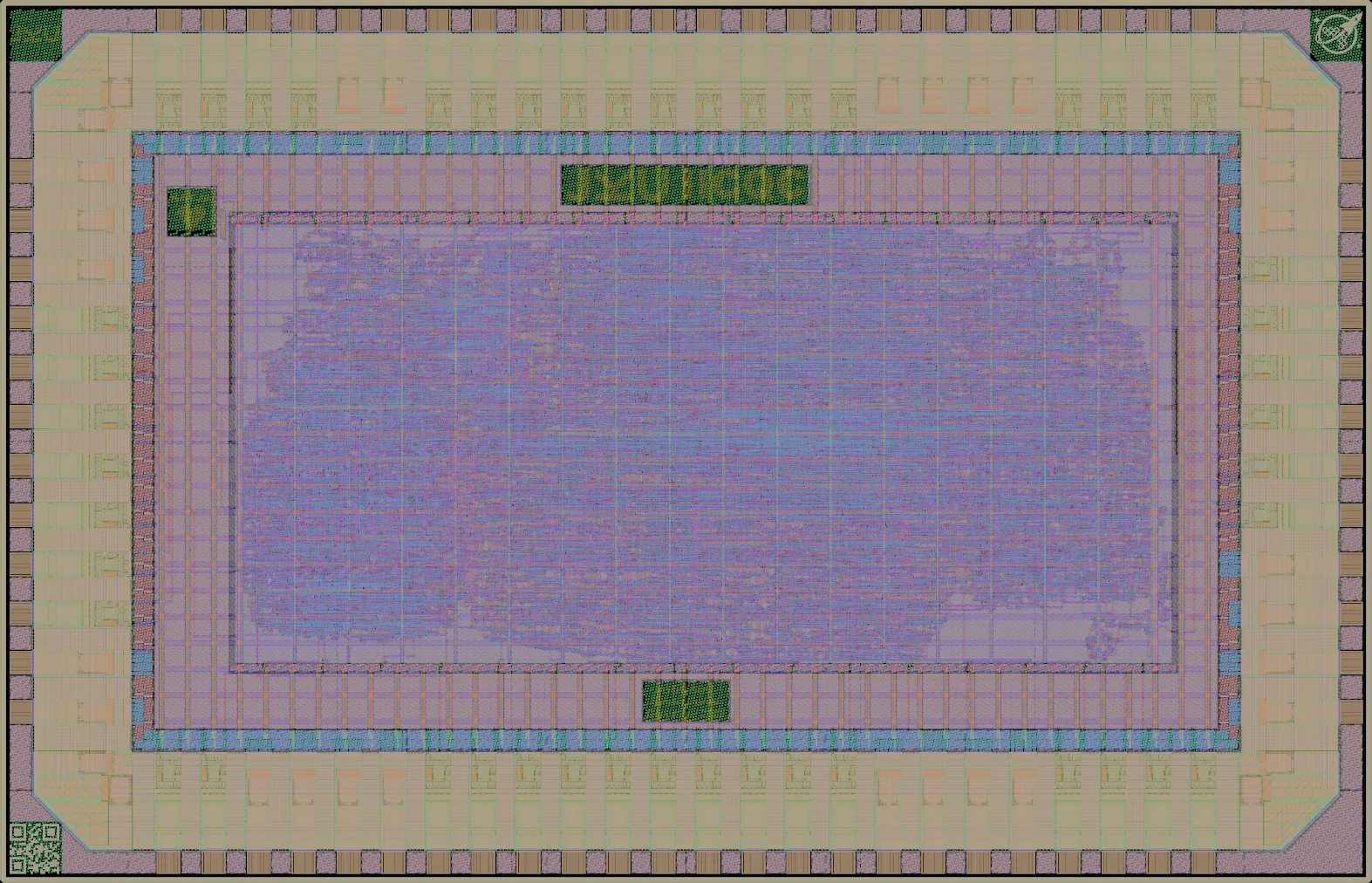
Rendered from the layout at 2.5 µm per pixel. Layers: NwellDiffusionPolysiliconMetal 1Metal 2Metal 3Metal 4Metal 5Top metalPad openings
Logic density
| Inside the core logic cells per mm² | 4k
(8% of buffer maximum) over the 5.02 mm² core: what the design itself packed |
|---|---|
| Inside the seal ring logic cells per mm² | 2k
over all 9.61 mm² of the slot, pad ring included |
| Densest mm² logic cells per mm² | 9k (15% of buffer maximum) |
| Core covered by logic | 19% |
| Transistor density transistors per mm² | 197k average, 207k in the mm² with the most logic cells |
Every figure here is measured from the public layout, the same way for every design on the run: see data and method, and how its designs used the process.
This wafer.space tapeout includes the digital core of an ATBS ADC from the IICQC at JKU.
GitHub Link: https://github.com/iic-jku/gf180mcu-jku-atbs-adc
Source repository Die photographBonding results
| Die | 3.93 × 2.53 mm (9.9 mm²) |
|---|---|
| Core area | 5.02 mm² inside the pad ring
as set in the design's own layout settings |
| Inside the seal ring | 9.61 mm² (the die less its 26 µm seal ring) |
| Placements | 1 on the reticle, in slot A1 |
| Bond pads | 72 |
| Transistors | 990,939 |
| Logic cells | 22,476 + 118,209 filler and tap cells |
| Libraries | 9t-5V (22k), 7t-5V (5) |
| SRAM | No SRAM |
Submission
| Licence | Apache-2.0 declared
Repository: SHL-2.1 in LICENSE, not the declared licence |
|---|---|
| Template | wafer-space/gf180mcu-project-template 1.3.5 |
| How it was checked | Commit and PDK pinThe licence and template were read from the repository at commit 2fae3a6c0ffd.The template release named above is the one whose Makefile pins the same PDK as that commit (PDK_TAG 1.6.6). |
| Chip-on-board | Not selected at submission · bonding results |
| Precheck | Passed
the check it was accepted on, 2025-12-17, gf180mcu-precheck 1.5.5 (from its image)
step results and logs |
Process features
Which parts of the GF180MCU process this design uses: its transistor voltages and where they come from, its gate oxides, and any devices drawn by hand outside the standard cells, SRAM and pads.
| 5 V | 9t-5V standard cells, 7t-5V standard cells |
|---|---|
| Gate oxides | Thick only (5 V/6 V) in the design itself |
| I/O library | gf180mcu_fd_io (733 cells), gf180mcu_ws_io (25 cells) |
Where the area went
How this design's area splits between logic cells, filler and tap cells, other and pad ring.
- Logic cells 0.93 mm² (9%)
- Filler and tap cells 3.70 mm² (37%)
- Other 0.39 mm² (4%)
- Pad ring 4.92 mm² (50%)
Most used cells
The ten standard cells this design uses most.
| Cell | Library | Instances | What it does |
|---|---|---|---|
| buf_1 | 9t-5V | 4,322 | Buffer |
| dffrnq_1 | 9t-5V | 3,246 | D flip-flop with reset |
| and2_1 | 9t-5V | 3,174 | 2-input AND gate |
| mux2_1 | 9t-5V | 2,948 | 2-input multiplexer |
| dlyd_1 | 9t-5V | 1,907 | Delay buffer |
| nand2_1 | 9t-5V | 791 | 2-input NAND gate |
| mux4_1 | 9t-5V | 782 | 4-input multiplexer |
| nor2_1 | 9t-5V | 631 | 2-input NOR gate |
| buf_2 | 9t-5V | 416 | Buffer (2x drive) |
| clkinv_1 | 9t-5V | 405 | Clock inverter |
Logic density map
Logic cells per mm² in each square millimetre of the die. Hatched outlines are SRAM macros; the red outline is the densest mm² that avoids them (9k logic cells per mm²), found by sliding a 1 mm square over the die in 0.1 mm steps, so it can straddle the fixed squares and find more than any one of them. Squares at the edges are partial, so they read low.
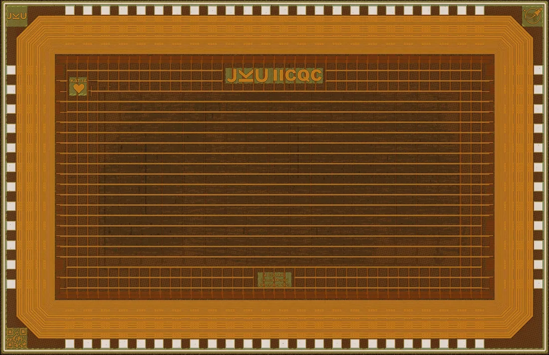
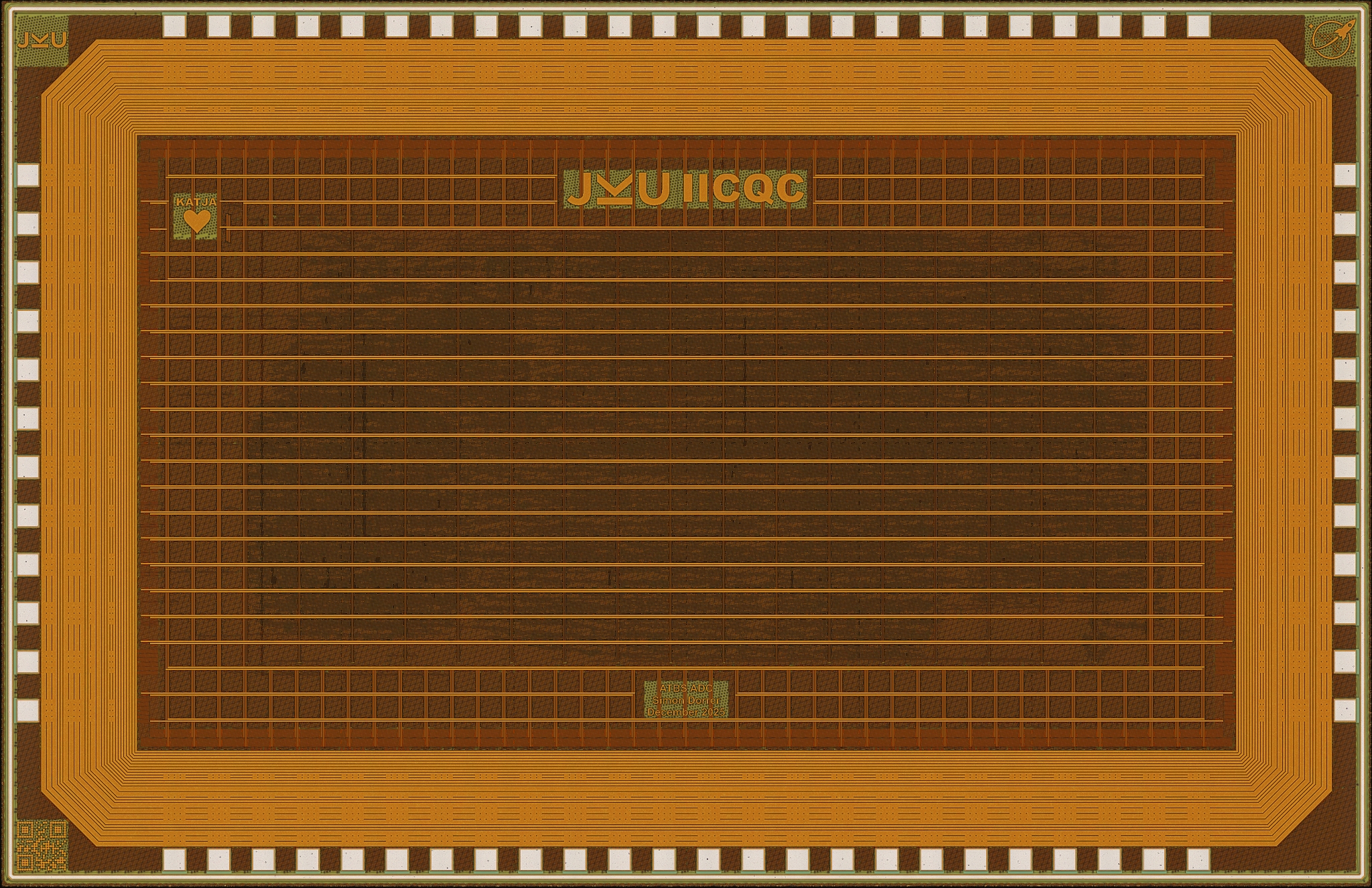
The fabricated die
A photograph of the finished chip, taken through a microscope after manufacture: optical micrograph © 2026 InfoSecDJ, CC BY-SA 4.0

Precheck
Before a design is made, the wafer.space platform checks it against the foundry's design rules. JKU2 was accepted on this check.
All 15 steps passed, with 0 KLayout DRC errors, on 2025-12-17.
Every step
| Step | Accepted on, and latest check 168, 2025-12-17, initial, gf180mcu-precheck 1.5.5 (from its image) PDK wafer-space/gf180mcu 1.6.6, LibreLane e2f0b0e |
|---|---|
| KLayout.ReadLayout | passed |
| KLayout.CheckTopLevel | passed |
| KLayout.CheckSize | passed |
| KLayout.GenerateID | passed |
| KLayout.Density | passed |
| Checker.KLayoutDensity | passed |
| KLayout.ZeroAreaPolygons | passed |
| Checker.KLayoutZeroAreaPolygons | passed |
| KLayout.Antenna | passed |
| Checker.KLayoutAntenna | passed |
| Magic.DRC | passed |
| Checker.MagicDRC | passed |
| KLayout.DRC | passed |
| Checker.KLayoutDRC | passed |
| KLayout.WriteLayout | passed |
| KLayout DRC errors | 0 |
| Magic DRC errors (advisory) | 0 |
| Files | steps · log (gzip) |
The steps of the gf180mcu-precheck LibreLane flow, as run by platform.wafer.space. The design was accepted on the newest finished check before it was submitted; later re-runs check the same file with updated rules. KLayout DRC is the sign-off check. Magic DRC is advisory: its count does not stop a design. In the logs, Magic's "Error while reading cell" lines about fill cells are messages from its reader, not check failures.