
Testing Dies#
With thousands of dies being produced in each run, and with every project being unique, how can we make sure that you get the best results and yield? There’s no single “does it work” check that fits everyone, so it turns testing into an interesting puzzle to solve. What do we test for? What’s common between them all?
Our community brainstormed for a solution, and we eventually landed on leveraging the ESD protection diodes that exist on the pad ring. We have started to build them into our flow.
The Theory#
An example protection circuit (from the GF180MCU PDK documentation)
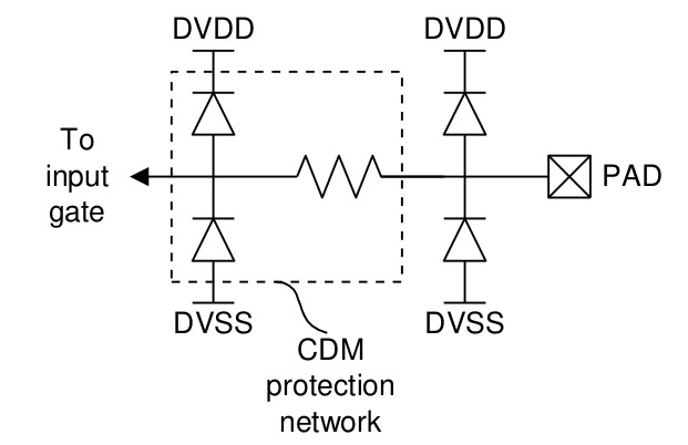
Each I/O pad has its own ESD protection, meaning that we can probe them to get a good idea whether the die is good or bad. Our approach is to inject a small constant current (~100µA) through the ground pad of the die, and measure the resulting voltage at each IO pad. A good bond produced a predictable forward-drop voltage, whereas missing or shorted bonds deviate from this expected behaviour.
By using a simple bring-up jig, we reduce the first power-up sequence to a simple and easily reproducible step which we can perform to verify that a die is alive, before any deeper, design-specific testing begins. For now, this testing is left as an exercise to the submitter!
We will share more of these approaches and their results in upcoming updates, so stay tuned in. (If that all sounds interesting, why not come join our Discord community to stay updated?)
Okay, we have a target to test, but how do we test them?
Prototyping the Testing Jig#
We prototyped many methods to reliably seat and release the mezzanine connectors that we use for the COB PCBs. This is important because a subpar connection could lead to a good die being marked as a fail, resulting in a lower yield.
Piggybacking off of the Tiny Tapeout demoboard, we were able to test and iterate until we felt confident that it would meet our needs.
Prototyping the 3D printed lever
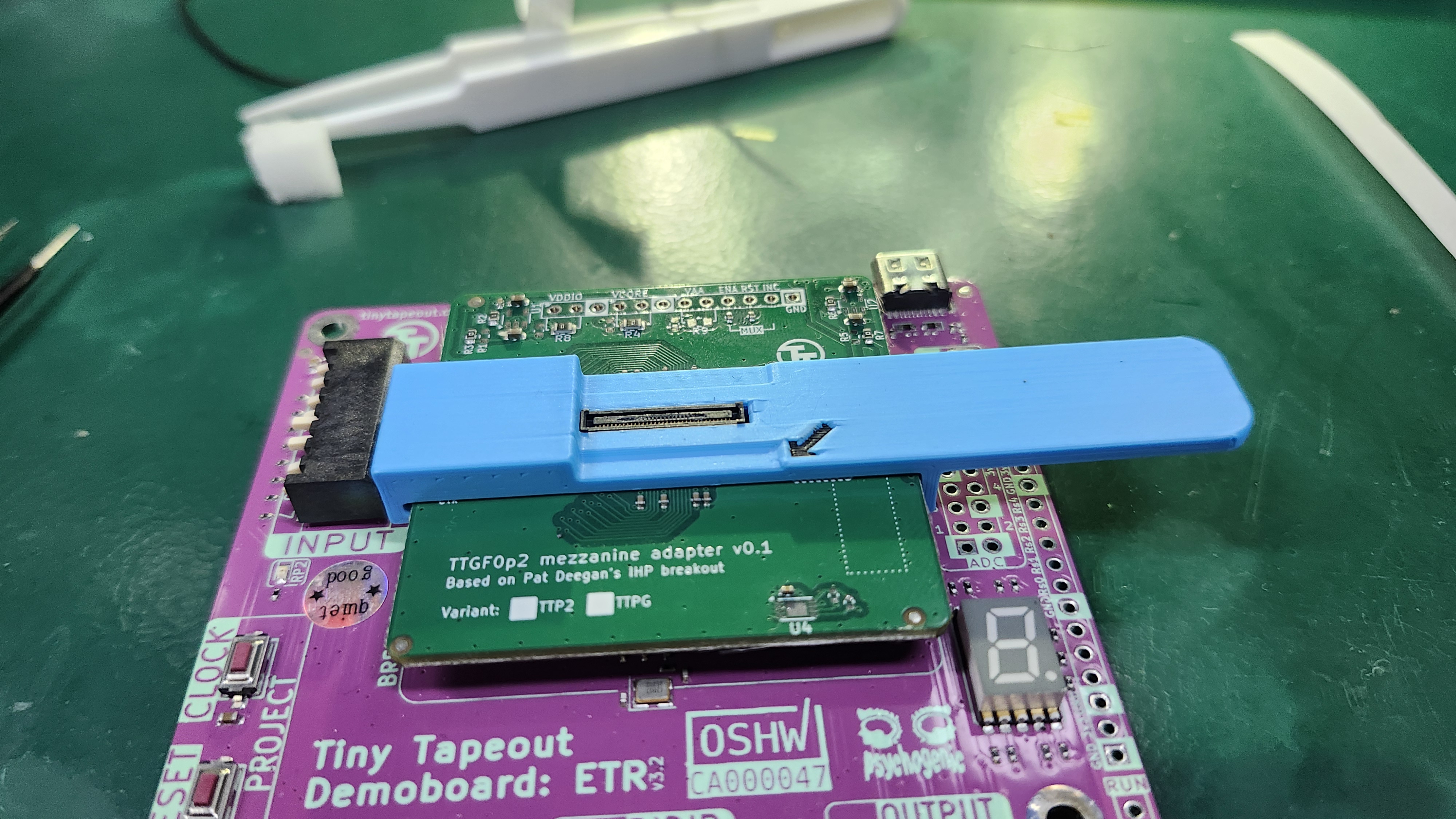
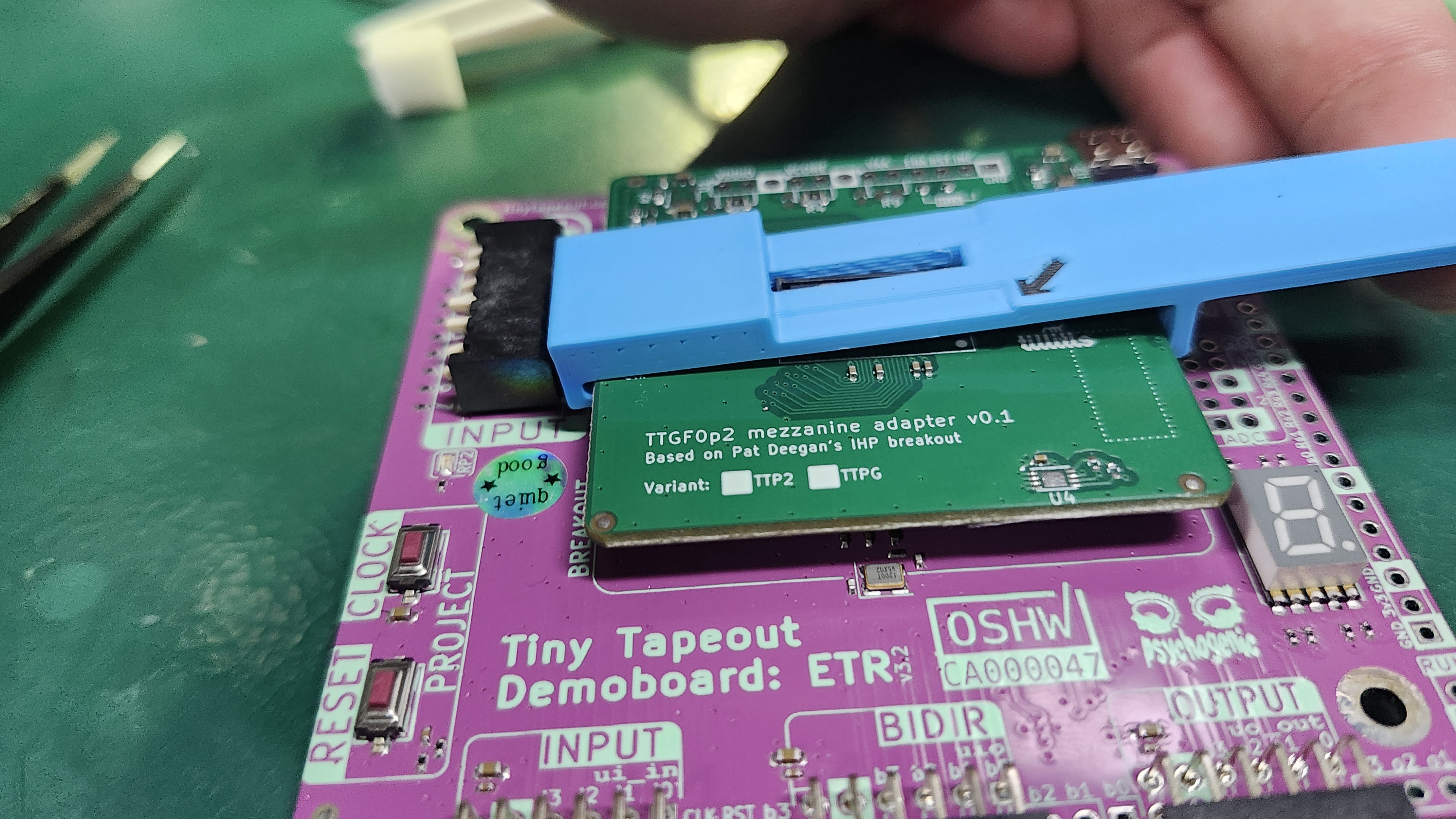
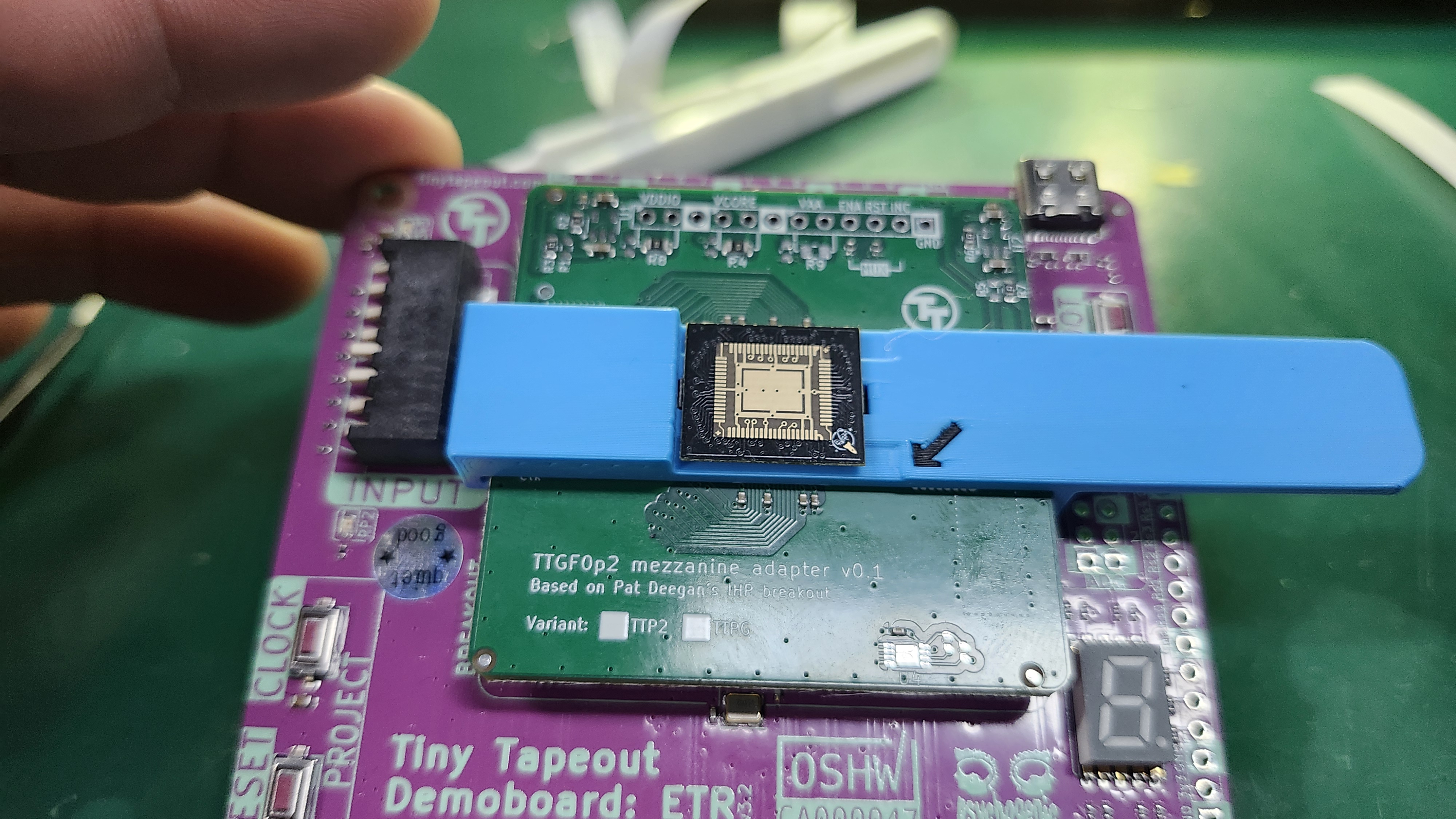
We finalised on the blue lever you see in the pictures above. With a mounting method now ready, all that remains is creating a bespoke testing jig which would suit our situation better. We started with a very simple setup - a breakout board which interfaces with the die under test, paired with a Raspberry Pi Pico 2.
A breakout board with a mounted COB alongside a Raspberry Pi Pico 2
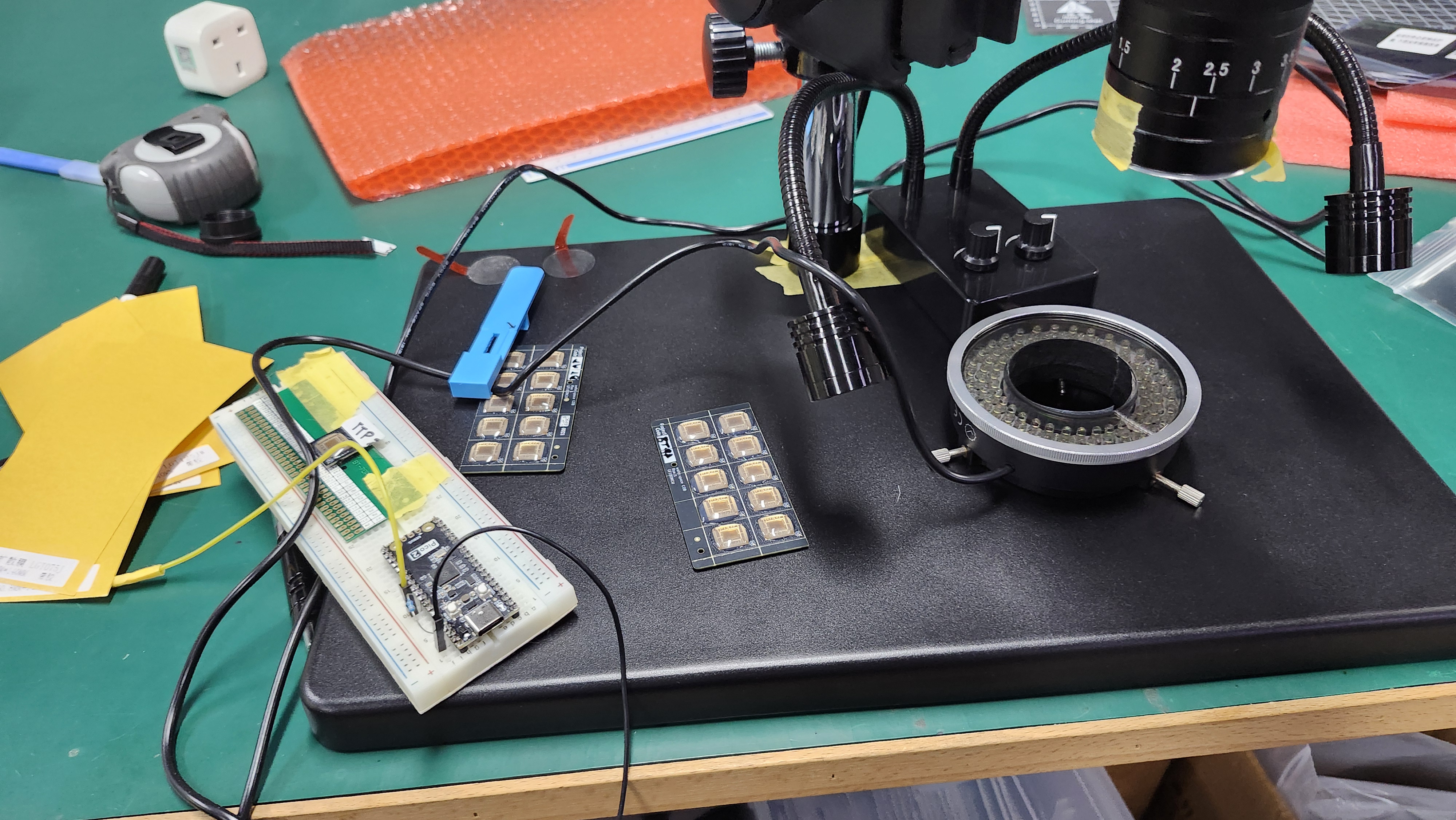
The goals for the jig are to:
- be easy to use
- capture images of the die under test
- test each pin
Keen-eyed readers may have noticed the microscope lens and lighting set up on which the Pico and COB are sitting upon. The goal of the microscope is to capture high quality images of failed wirebonds, allowing us and our wirebonding partner to improve upon the process in order to further increase the yield. We want these chips to be perfect when they get to you, so we’re pulling out all the stops!
Version 1 of the Testing Jig#
Introducing the (aptly named) BondTest72 - the latest in open source wirebond testing jig equipment for GF180 tapeouts!
BondTest72 contains everything we need to check whether the die is properly wirebonded, including checking for neighbouring shorts. Thank you Lauri Mihkels for bringing this to life. PCB schematics are available on GitHub: github.com/szfate/BondTest72.
BondTest72 self-test
BondTest72 and an adapter board (Mezzanine70) for COBs
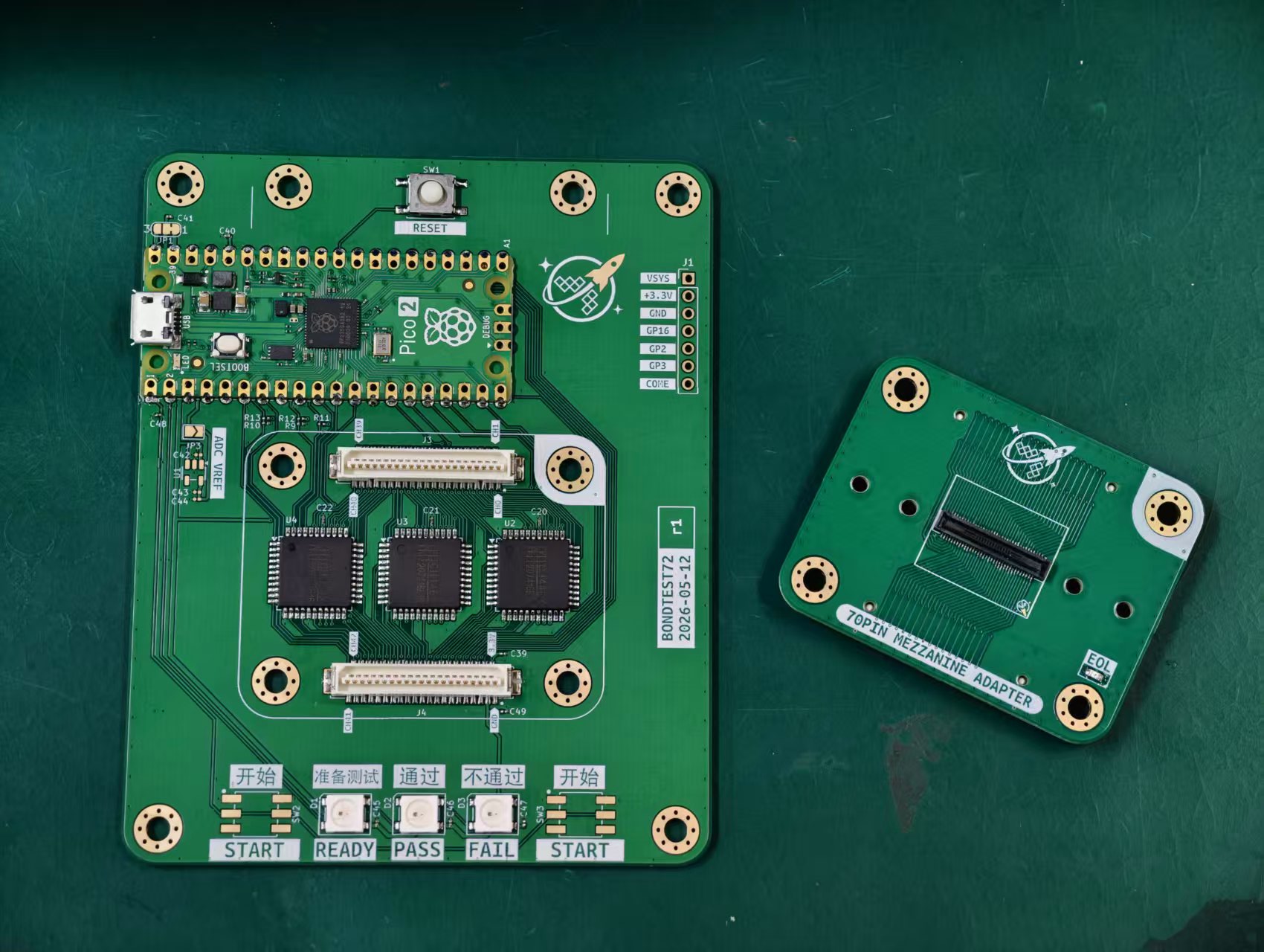
It is packed with the Raspberry Pi Pico 2 for the brains of the operation, three CH446X multiplexers to access
all available pins, and three RGB LEDs for easy status readout - READY, PASS and FAIL. The adapter board contains
an AT21CS01 EEPROM which stores manufacturing metadata such as hardware ID, padring info and total insertion count.
Testing Sequence#
Each pad is tested in two phases, which catches bond defects and inter-pad shorts.
-
Neighbour phase - the pad under test is grounded and its immediate ring-neighbours are sensed via a resistor divider. A low reading indicates an inter-pad short.
-
Injection phase - current is injected via the ground pad and the voltage is measured on an ADC bus. A good bond reads between 0.2 - 0.8 V, whereas an open bond is >2.5 V and a short is < 0.1 V.
Reading the Results#
The RGB LEDs indicate whether a die has passed or failed, but the firmware is far more capable. If the jig is connected to a PC, then you can access real-time information whilst a die is being tested. It provides readings per-pad, which can be used to build an image of passing or failing pads.
A GUI program indicating passing/failing pads, accompanied with voltage readings per pad
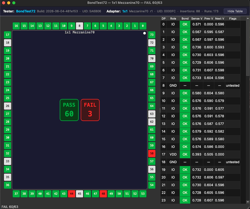
Fantastic stuff! Incredible information to have access to should we ever need to diagnose a fault or a systemic issue.
Capturing a die image during pad tests to identify bad bonds
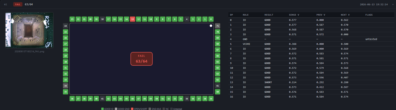
Pairing the jig with a microscope allows us to capture close up images automatically too, meaning we can visually inspect the die and confirm the results.
Join us!#
We hoped you enjoyed reading this update, we’re so grateful to have a community that can come together and solve these tough engineering challenges.
If you’d like to be a part of it, we’re active on the wafer.space Discord and on Matrix at #gf180mcu.
Run #3 is Live#
Run #3 slots are available on Crowd Supply until 9 December 2026, but early bird pricing ends 30 September 2026! Slots start from just $2/die with early bird pricing, so get in early and have 1,000 of your very own chips made affordably.
Chip-on-board packaging is available as an add-on for $1,500 ($1.50/die).