Google GF180MCU open shuttle (GFMPW‑0) · Run by Google and Efabless
EduRISC16
E91D · RISC-V and CPUs · 1 × 1 slot
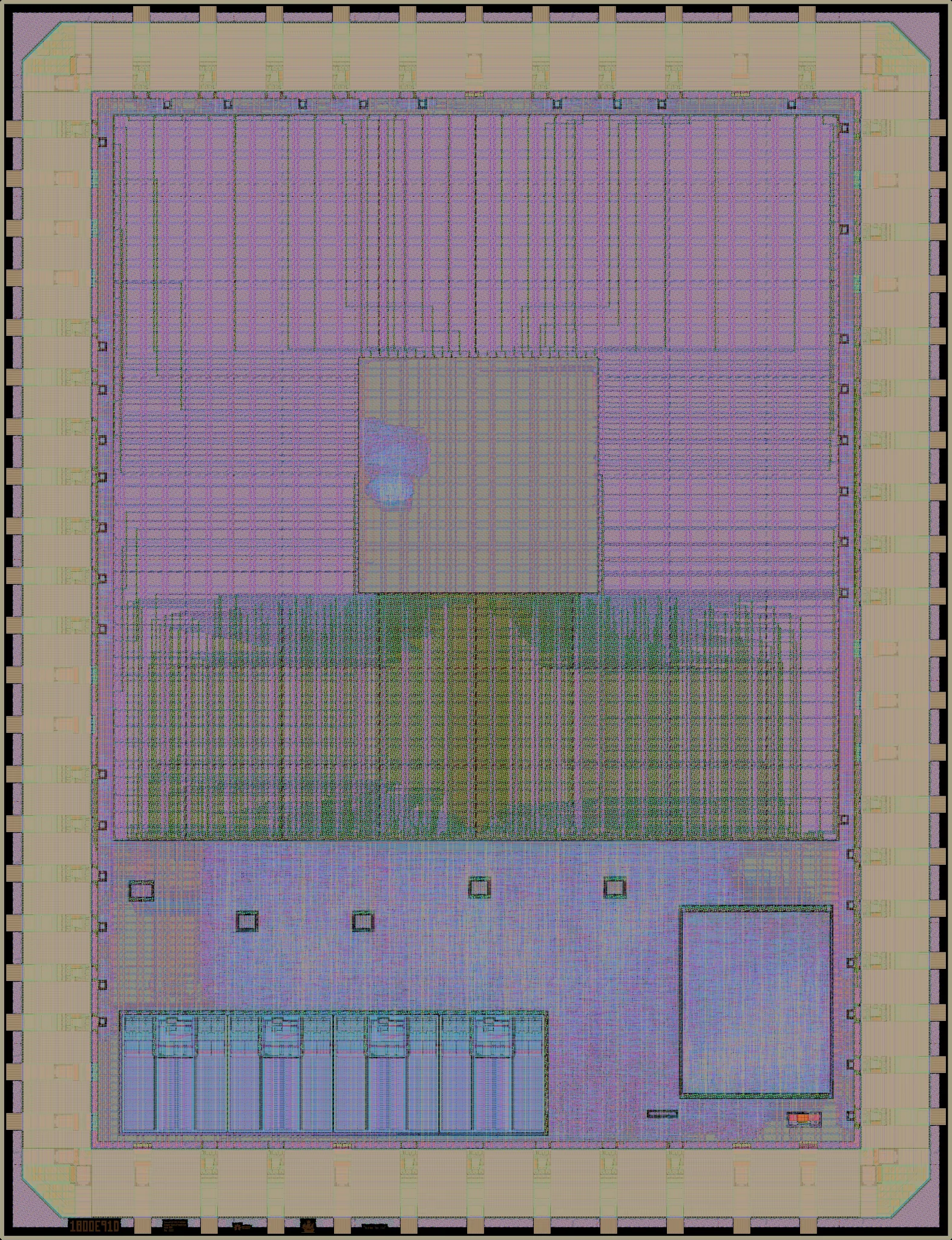
Rendered from the layout at 2.5 µm per pixel. Layers: NwellDiffusionPolysiliconMetal 1Metal 2Metal 3Metal 4Metal 5Top metalPad openings
Logic density
| Core average logic cells per mm² | <1k (<1% of buffer maximum) |
|---|---|
| Densest mm² logic cells per mm² | 2k (3% of buffer maximum) |
| Core covered by logic | <1% |
| Transistor density transistors per mm² | 23k average, 189k in the mm² with the most logic cells |
Every figure here is measured from the public layout, the same way for every design on the run: see data and method, and how its designs used the process.
A 16-bit RISC themed processor for educational purposes. By Ryan Price.
| Die | 3.93 × 5.12 mm (20.1 mm²) |
|---|---|
| Core area | 9.00 mm² inside the pad ring
its user_project_wrapper cell |
| Placements | 1 on the reticle, in slot C3 |
| Bond pads | 63 |
| Transistors | 207,791 |
| Logic cells | 2,034 + 31,767 filler and tap cells |
| Libraries | 7t-5V (2k) |
| SRAM | No SRAM |
Process features
Which parts of the GF180MCU process this design uses: its transistor voltages and where they come from, its gate oxides, and any devices drawn by hand outside the standard cells, SRAM and pads.
| 5 V | 7t-5V standard cells |
|---|---|
| Gate oxides | Thick only (5 V/6 V) in the design itself |
Where the area went
How this design's area splits between logic cells, filler and tap cells, other and outside the user area.
- Logic cells 0.04 mm² (<1%)
- Filler and tap cells 0.91 mm² (5%)
- Other 8.04 mm² (40%)
- Outside the user area 11.12 mm² (55%)
Most used cells
The ten standard cells this design uses most.
| Cell | Library | Instances | What it does |
|---|---|---|---|
| xor2_1 | 7t-5V | 228 | 2-input XOR gate |
| clkbuf_1 | 7t-5V | 218 | Clock buffer |
| nand2_1 | 7t-5V | 194 | 2-input NAND gate |
| nor2_1 | 7t-5V | 184 | 2-input NOR gate |
| buf_1 | 7t-5V | 138 | Buffer |
| aoi21_1 | 7t-5V | 134 | AND-OR-Invert compound gate |
| oai21_1 | 7t-5V | 118 | OR-AND-Invert compound gate |
| xnor2_1 | 7t-5V | 94 | 2-input XNOR gate |
| and2_1 | 7t-5V | 60 | 2-input AND gate |
| clkinv_1 | 7t-5V | 55 | Clock inverter |
Logic density map
Logic cells per mm² in each square millimetre of the die. Hatched outlines are SRAM macros; the red outline is the densest mm² that avoids them (2k logic cells per mm²), found by sliding a 1 mm square over the die in 0.1 mm steps, so it can straddle the fixed squares and find more than any one of them. Squares at the edges are partial, so they read low.