Tiny Tapeout GF 0.2 · Die TTP2 on wafer.space Run 1: the standard edition
WokwiPWM
547 · Other digital · 1 × 1 tile
by Ken Pettit · repository @kdp1965
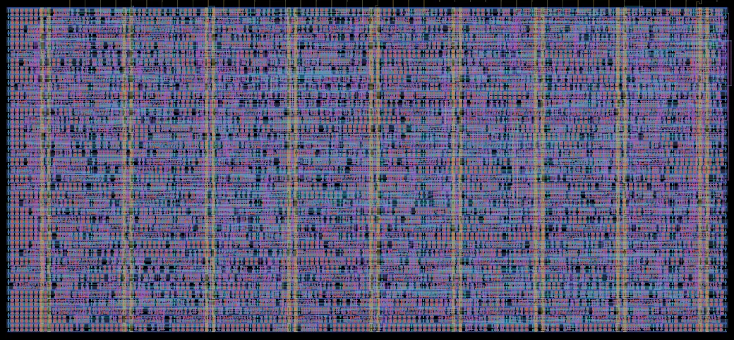
Rendered from the layout at 0.33 µm per pixel. Layers: NwellDiffusionPolysiliconMetal 1Metal 2Metal 3Metal 4Metal 5Top metalPad openings
Logic density
| Core average logic cells per mm² | 26k (35% of buffer maximum) |
|---|---|
| Densest 0.1 mm square logic cells per mm² | 33k (43% of buffer maximum) |
| Core covered by logic | 69% |
| Transistor density transistors per mm² | 285k average, 312k in the 0.1 mm square with the most logic cells |
Every figure here is measured from the public layout, the same way for every design on the chip: see data and method, and how its designs used the process.
A 4-channel PWM impelemented in PWM gates
Source repository Its page on Tiny TapeoutBuy this chip
| Size | 347 × 161 µm (0.056 mm²) |
|---|---|
| Macro | tt_um_wokwi_445338187869298689 |
| Files | documentation · licence · layout and netlist in Tiny Tapeout GF 0.2 |
| Tiles | 1 × 1 at column 2, row 19 of the tile grid |
| Mux address | 547 |
| Language | Wokwi |
| Clock | 10 kHz |
| Built with | LibreLane 2.4.2, open_pdks 0fe599b2afb6 |
| Transistors | 15,974 |
| Logic cells | 1,481 + 1,814 filler and tap cells |
| Libraries | 7t-5V (1k) |
| SRAM | No SRAM |
Process features
Which parts of the GF180MCU process this design uses: its transistor voltages and where they come from, its gate oxides, and any devices drawn by hand outside the standard cells, SRAM and pads.
| 5 V | 7t-5V standard cells |
|---|---|
| Gate oxides | Thick only (5 V/6 V) in the design itself |
Where the area went
How this project's area splits between logic cells, filler and tap cells and other.
- Logic cells 0.04 mm² (69%)
- Filler and tap cells 0.01 mm² (24%)
- Other 4,033 µm² (7%)
Most used cells
The ten standard cells this design uses most.
| Cell | Library | Instances | What it does |
|---|---|---|---|
| clkinv_1 | 7t-5V | 414 | Clock inverter |
| mux2_2 | 7t-5V | 201 | 2-input multiplexer (2x drive) |
| dffrnq_1 | 7t-5V | 196 | D flip-flop with reset |
| and2_1 | 7t-5V | 164 | 2-input AND gate |
| nor2_1 | 7t-5V | 124 | 2-input NOR gate |
| nand2_1 | 7t-5V | 113 | 2-input NAND gate |
| or2_1 | 7t-5V | 77 | 2-input OR gate |
| clkbuf_8 | 7t-5V | 28 | Clock buffer (8x drive) |
| buf_2 | 7t-5V | 24 | Buffer (2x drive) |
| xnor2_1 | 7t-5V | 24 | 2-input XNOR gate |
Logic density map
Logic cells per mm² in each 0.1 mm square of the project (counted in the square, scaled up to a mm²). Hatched outlines are SRAM macros; the red outline is the densest 0.1 mm square that avoids them (33k logic cells per mm²), found by sliding a 0.1 mm square over the project in 20 µm steps, so it can straddle the fixed squares and find more than any one of them. Squares at the edges are partial, so they read low.
Tiny Tapeout and wafer.space are independent companies that work together (announcement). Tiny Tapeout runs its own shuttles: it takes the projects, builds the die, and sells and supports the chips and boards. wafer.space has the dies manufactured on its GF180MCU runs, and these pages are wafer.space's measurements of them. For anything about a Tiny Tapeout project, chip or order, contact Tiny Tapeout.